This also applies to cable, chain, and webbing.
Gear that is anchored includes anchors, rocks, trees, tripods, trucks, etc.
A "bight" is a simple loop in a rope that does not cross itself.
A "bend" is a knot that joins two ropes together. Bends can only be attached to the end of a rope.
A "hitch" is a type of knot that must be tied around another object.
"Descending devices" (e.g., ATCs, Brake Bar Racks, Figure 8s, Rescue 8s, etc) create friction as their primary purpose. The friction in descending devices is always considered when calculating forces.
The "Safety Factor" is the ratio between the gear's breaking strength and the maximum load applied to the gear (e.g., 5:1).
The Forces page in the Gear Builder controls how forces are calculated on the gear. The options on the Forces page are only available if the gear has gear connections or can connect to ropes.

Select this checkbox if the gear is an anchor. This option is only available when the Can pull or release rope option is not selected and the gear can connect to other gear or ropes.
Anchored gear never has a weight and does not move during force calculations.
This is an advanced feature that controls where the forces will be measured. In almost all cases, you can simply select the Use default tension midline checkbox. Learn more about the tension midline.

Select this checkbox if the gear can pull or release ropes. This option is not available if the Is descending device or Is a knot options are selected.
This option is used for hands, winches, and images of people who are pulling (or releasing) rope. It should not be set for other gear (such as a load) that applies force on a rope but does not actually pull the rope. Gear that has the "can pull or release" option set is treated much differently during force calculations.
Learn more about gear that can pull or release rope.
Select this checkbox if the gear is a descending device. vRigger always considers friction on descending devices regardless of the Consider Friction checkbox on the Forces toolbar.
This option is only available when the Can pull or release rope, Is a ratchet device, Is a knot, and Can only connect to the end of a rope options are not selected, and the gear can connect to rope.
Select this checkbox if the gear is a knot. Knots always have 100% friction. This option is only available when the Can pull or release rope, Is a descending device, and Is a ratchet device options are not selected, and the gear can connect to rope.
The graphic images used for knots should be green because the green portions of knots are replaced with the rope's color. Refer to the Arrange Rope Segments command to learn how, with some skill, you can draw knots using vRigger.
This checkbox identifies gear that allows the rope to slide freely in one direction but prevents it from moving in the opposite direction. An identical checkbox exists on the Ropes page of the Gear Builder. Learn more about ratchet devices.

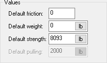
Specify the default friction for this gear.
This option specifies the default friction when the gear is added to the workspace. After the gear is added to the workspace you can change its friction in the properties pane.
This option is only available when the Can pull or release rope option is not selected, the gear can connect to rope, and it does not connect to the end of rope.
Specify the default weight of this gear. This option is only available when the Can pull or release rope and Is an anchor options are not selected.
This option specifies the default weight (mass, really) of the gear when it is added to the workspace. After the gear is added to the workspace you can change its weight in the properties pane.
Specify the default breaking strength of this gear.
This option specifies the default breaking strength when the gear is added to the workspace. After the gear is added to the workspace you can change its strength in the properties pane.
The maximum, and default, strength is 100 kN (approximately 22,000 lb or 10,000 kg).
This option is only available if the gear connects to rope or if it has connections on the Connection page and the connections are not to fire hose.
Specify the default maximum force that gear that can pull or release rope can pull.
This option specifies the default maximum force when gear that can pull or release rope is added to the workspace. After the gear is added to the workspace you can change its maximum force in the Force (Pull/Release) section of the properties pane.
This option is only available when the Can pull or release rope option is selected and the gear can connect to rope.
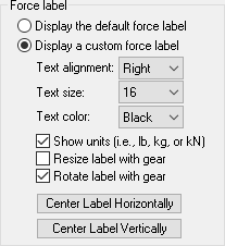
This section allows you to customize how force labels are displayed next to this piece of gear. These options are only available if the gear connects to rope or if it has connections on the Connection page and the connections are not to fire hose.

Select this checkbox to display the forces in their default location (i.e., to the right of the gear).
Select this checkbox to customize the force label. After selecting this option, you can drag the force label in the Gear Builder to a new location and can change several additional options (e.g., text alignment, text size, text color, etc), as explained below.
The forces on the following load cell were displayed using a custom force label. The customization allows the forces to be displayed in the correct location even if the load cell is rotated or resized.

Specify whether the force label should be aligned to the left, center, or right.
This option is only available when the Display a custom force label option is selected.
Specify the size of the force label (the default size is 10). The Resize label with gear option also affects the size of the label.
This option is only available when the Display a custom force label option is selected.
Specify the color of the force label.
This option is only available when the Display a custom force label option is selected.
Select this checkbox if you want the units (i.e., lb, kg, or kN) displayed after the force label. The Units option on the Forces toolbar controls which units are displayed.
This option is only available when the Display a custom force label option is selected.
Select this checkbox if you want the size of the force label to change when you resize the gear. If you are displaying the forces on top of the gear (e.g., on the load cell shown above), you will probably want to select this option. If you are displaying the forces to the side of the gear, you will probably want to leave this option unselected.
This option is only available when the Display a custom force label option is selected.
Select this checkbox if you want the force label to rotate when you rotate the gear. As with the Resize label with gear option, if you are displaying the forces on top of the gear (e.g., on the load cell shown above), you will probably want to select this option. If you are display the forces to the side of the gear (as is typical with most gear), you will probably want to leave this option unselected.
This option is only available when the Display a custom force label option is selected.
Click these buttons to quickly center the force label horizontally or vertically on the gear. You can then use your mouse to drag the label to a new location.
These buttons are only available when the Display a custom force label option is selected.