This also applies to cable, chain, and webbing.
Gear that is anchored includes anchors, rocks, trees, tripods, trucks, etc.
A "bight" is a simple loop in a rope that does not cross itself.
A "bend" is a knot that joins two ropes together. Bends can only be attached to the end of a rope.
A "hitch" is a type of knot that must be tied around another object.
"Descending devices" (e.g., ATCs, Brake Bar Racks, Figure 8s, Rescue 8s, etc) create friction as their primary purpose. The friction in descending devices is always considered when calculating forces.
The "Safety Factor" is the ratio between the gear's breaking strength and the maximum load applied to the gear (e.g., 5:1).
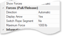
The Forces (Pull/Release) section of the properties pane allows you to modify information that is specific to gear that can pull or release rope.

The Direction field lets you specify whether the item is pulling, releasing, or holding the rope. If you choose Automatic, vRigger will determine if the item is pulling or releasing based on the gear that is on the rope.
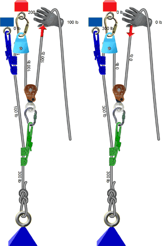
Consider the following two systems. In the 3:1 system on the left, the hand is pulling the load and is therefore holding one-third of the load (i.e., 100 pounds). In the identical system on the right, the hand is releasing rope, the Prusik is holding all of the load, and the hand is holding 0 pounds.

Whether an item is pulling or releasing rope also changes how friction affects forces. When pulling, friction increases the forces on the item that is pulling. When releasing, friction decreases forces on the item that is releasing.
If you select Holding, vRigger will treat the puller similar to an anchor. Learn more here.
The Display Arrow field specifies whether an arrow should be displayed showing the direction the rope is moving (i.e., pulling or releasing). The arrow is only displayed when the forces have been calculated. If you change anything in the system and the forces are no longer valid, the arrow will no longer be displayed. The arrow helps you understand the direction the rope is moving and which rope segment is being pulled or released. This option allows you to hide the arrow.
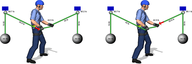
The Switch Rope Segment setting instructs vRigger to pull/release the other rope segment that is connected to the selected item. In the illustration on the left, the man is pulling on the rope segment that is behind him. In the illustration on the right, the Switch Rope Segment property was used to pull on the rope segment that is in front of him. You can see that the forces on the rope segments vary based on the direction the rope is moving due to friction.

The Maximum Force setting controls the maximum force that the item can pull or release during force calculations. In most systems, the puller's maximum is never reached. However, in the following example, the hand's force must be limited or it will pull until the rope breaks. In this example, the hand's maximum force was set to 2,000 lb.

As with other gear, you can also set the Strength of pullers in the properties pane. The Strength setting primarily affects the puller's safety factor. For example, you might set the Maximum Force of a single rescuer to 2000 lb so forces would be calculated, but set the Strength to 50 lb.