

This also applies to cable, chain, and webbing.
Gear that is anchored includes anchors, rocks, trees, tripods, trucks, etc.
A "bight" is a simple loop in a rope that does not cross itself.
A "bend" is a knot that joins two ropes together. Bends can only be attached to the end of a rope.
A "hitch" is a type of knot that must be tied around another object.
"Descending devices" (e.g., ATCs, Brake Bar Racks, Figure 8s, Rescue 8s, etc) create friction as their primary purpose. The friction in descending devices is always considered when calculating forces.
The "Safety Factor" is the ratio between the gear's breaking strength and the maximum load applied to the gear (e.g., 5:1).
The Forces page of the Gear Builder has an advanced feature that lets you specify where the item's forces should be measured. This is done by specifying the gear's "tension midline." In almost all cases, you should simply leave the Use default tension midline checkbox selected. However, in a few cases you may want to modify the midline to change where the forces are measured on gear that you create.
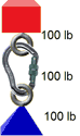
In the following illustration, it is obvious that the carabiner should display 100 lbs of force. The load is "pulling" down with 100 lbs of force and the anchor is "pulling" the carabiner up with 100 lbs of force. The 100 lbs displayed is the "tension" across the carabiner.
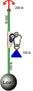
Now consider this next system. It contains a 100 lb load hanging on a rope and a second 100 lb load attached to the rope with an ascender. The net force on the anchor is obviously 200 lbs, but what force is on the ascender?
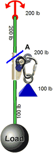
If the rope was connected firmly to both the top and bottom of the ascender, there would be 200 lbs of force "pulling" down on the ascender (i.e., 100 lbs from the bottom rope plus 100 lbs from the small blue load that is attached with a carabiner). The blue line in the following illustration (labeled "A") shows where the tension would be measured on the ascender. In this case, the ascender displays 200 lbs. Remember that this assumes that the rope is connected to both the top and bottom of the ascender rather than passing through it.
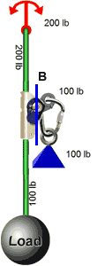
In reality, the rope passes through the ascender and doesn't create additional "tension" within the ascender. However, the 100-pound blue load does create downward force on the arm protruding from the ascender. The blue line in this next illustration (labeled "B") shows where the tension should be measured on the ascender. In this case, the ascender will display 100 lb.
The blue lines in the above two illustrations show possible locations where the forces can be measured on the ascender (i.e., the "tension midline"). The tension midline is displayed on the Forces page of the Gear Builder when the Use default tension midline checkbox is unchecked. When this box is unchecked, you can drag the handles on the ends of the tension line.
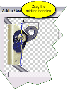
In almost all cases, you can simply select the Use default tension midline checkbox. In the few cases where the default tension does not display the desired force (such as on the ascender shown above), you can uncheck this box and drag the tension midline to the desired location.