This also applies to cable, chain, and webbing.
Gear that is anchored includes anchors, rocks, trees, tripods, trucks, etc.
A "bight" is a simple loop in a rope that does not cross itself.
A "bend" is a knot that joins two ropes together. Bends can only be attached to the end of a rope.
A "hitch" is a type of knot that must be tied around another object.
"Descending devices" (e.g., ATCs, Brake Bar Racks, Figure 8s, Rescue 8s, etc) create friction as their primary purpose. The friction in descending devices is always considered when calculating forces.
The "Safety Factor" is the ratio between the gear's breaking strength and the maximum load applied to the gear (e.g., 5:1).
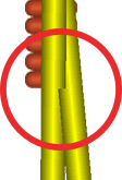
Sometimes ropes may appear to pass through other rope. This is usually less apparent on printouts and in presentations than it is on the screen.

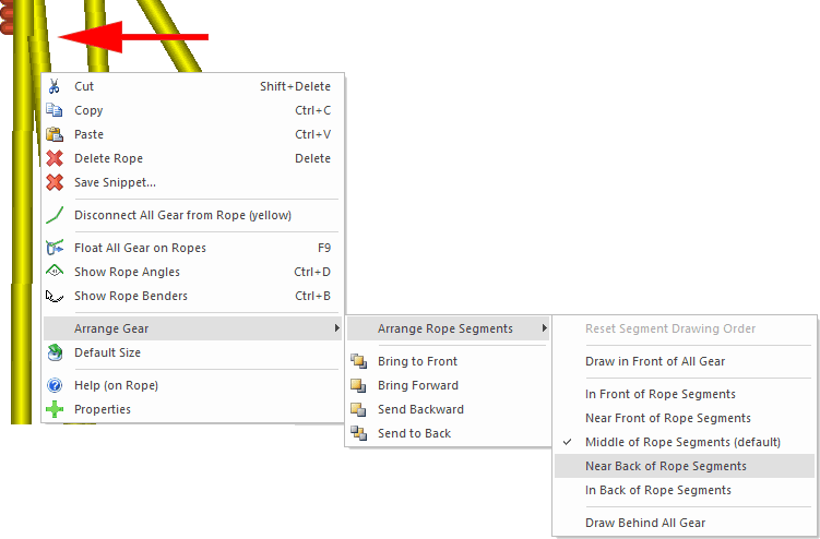
There is a possible solution, that is appropriate for vRigger power users, which is to change the drawing order of the individual rope segments. To do this, you first need to make sure the advanced "rope arrangement commands" are enabled on the General page of the Options dialog.
With the "rope arrangement commands" enabled, right-click on one of the intersecting rope segments and choose Arrange Gear > Arrange Rope Segments and then choose to draw the rope segment further forward or backward, as appropriate.

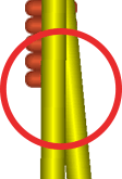
In the above case, we chose to move the selected rope segment "near (the) back of rope segments." This fixed the cosmetic problem.

As mentioned on the page that discusses the gear drawing order, it is important to wait until you finish designing your system before changing the drawing order. Once you manually change the drawing order, any new gear you add to the workspace will be added in front of the existing gear. When in doubt, click the Auto Arrange button on the Home to have vRigger automatically arrange the gear, and then, if necessary, use the "arrangement" commands on a few pieces of gear or rope segments.